


Getting Started
The Number Written on the Drawing Is the Building. The Distance You Measure on the Paper Is Not.
A 60 foot wall at quarter inch scale is 15 inches of ink. Print it "fit to page" on tabloid and it reads 55 feet, which is wrong by five feet and plausible enough to build. Here is how to read a set so that never happens.
American Barndos Editorial — 13 min read
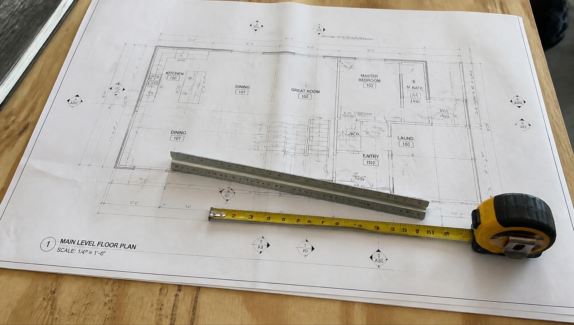
A 60 foot wall drawn at quarter inch scale is exactly 15 inches of ink. Print that sheet on tabloid paper with "fit to page" checked and it becomes 6.875 inches, and anyone who measures it with a half size scale reads 55 feet. Not an obviously broken number. A perfectly plausible one, five feet short, and plausible is what gets built.
Start here
Almost everyone opens a plan set to the floor plan, looks at the room layout, and closes it. That is shopping, not reading.
The floor plan is the sheet that sells the house and it is close to the least informative sheet in the set. It tells you where the walls are. It does not tell you what the walls are, how they are built, what holds up the roof over them, or which of the dimensions on it are the ones the framer is actually going to hold.
Reading a set means four different things, in this order:
- Finding the sheet you need, which the numbering system tells you if you know how it works.
- Knowing which of the four views you are looking at, because a plan, an elevation, a section, and a detail are the same building cut four different ways.
- Reading the dimensions correctly, which is a discipline, not a skill.
- Following the callouts, because a construction set is a hyperlinked document that predates hyperlinks.
Everything below is those four things. What you actually receive when you buy a plan set, which sheets are included and which are deliberately not, is covered in the plans article and linked at the end.
The sheet number tells you where you are
Construction sets are numbered under a national convention, and once you know it you can find any sheet without opening the index.
A sheet number looks like A-301. It has two parts.
The letter is the discipline. Who drew it.
| Letter | Discipline |
|---|---|
| G | General |
| V | Survey and mapping |
| B | Geotechnical |
| C | Civil |
| L | Landscape |
| S | Structural |
| A | Architectural |
| I | Interiors |
| F | Fire protection |
| P | Plumbing |
| M | Mechanical |
| E | Electrical |
| T | Telecommunications |
| Z | Contractor and shop drawings |
The bolded ones are the disciplines that show up on a typical residential build. The full standard has more than twenty.
The first digit after the letter is the type of drawing. What kind of view it is.
| Digit | Sheet type |
|---|---|
| 0 | General: symbol legend, abbreviations, general notes |
| 1 | Plans |
| 2 | Elevations |
| 3 | Sections |
| 4 | Large scale plans, elevations and sections |
| 5 | Details |
| 6 | Schedules and diagrams |
| 9 | Three dimensional views, isometrics, perspectives, photos |
So A-301 is architectural, sections. S-101 is structural, plans. E-601 is electrical, schedules. A-001 is where the legend lives, and it is the sheet nobody opens and everybody should.
Two practical consequences.
If a sheet you expect is not in the set, the letter tells you who is missing. No S sheets means no structural drawings. No M or P sheets means nobody has designed the mechanical or plumbing. That is normal for a stock plan set and it is exactly the gap the plans article covers.
Small residential sets frequently compress this. A barndominium set may run eight to fifteen sheets and use a simplified numbering like A1, A2, A3. The convention still holds directionally: plans come before elevations, elevations before sections, sections before details, and schedules land at the back.
Plan, elevation, section, detail
Four views. Same building. The difference is where the imaginary knife went and where you are standing.
| View | The cut | What it is good for |
|---|---|---|
| Plan | Sliced horizontally, roughly four feet up, looking down | Where things are in relation to each other. Layout, dimensions, room sizes |
| Elevation | Not cut. Standing outside, looking straight at one face | What the building looks like. Heights, roof pitch, grade, exterior materials, window and door placement |
| Section | Sliced vertically through the whole building, looking sideways | How the building stacks. Floor to ceiling heights, roof framing, how the assemblies meet |
| Detail | A small piece of a section, blown up | How it is actually built at the connection. This is where the real information is |
The mistake worth naming: people read plans and elevations and skip sections and details. Plans and elevations are the pretty ones. Sections and details are where a builder finds out what you actually specified, and a set with thin details is a set that will generate questions in the field, which is another way of saying change orders.
An elevation, incidentally, is a flat projection and not a perspective. It does not look the way the building will look to your eye standing in the yard. Nothing recedes, nothing converges. That is deliberate, because you can measure an elevation and you cannot measure a perspective.
Scale, and the one rule that matters
Different sheets in one set use different scales, and that is where people get caught.
| Scale | Typically used for |
|---|---|
| 1/8" = 1'-0" | Overview plans, large buildings. More building on the sheet, smaller detail |
| 1/4" = 1'-0" | The standard residential floor plan scale |
| 1/2" = 1'-0" | Small plans, kitchens, baths, where you need to check carefully |
| 3/4" = 1'-0" | Tight areas, millwork |
| 1" = 1'-0" and larger | Details and assemblies, where the junction matters more than the layout |
Now the rule, and it is the single most important sentence here:
Written dimensions govern. Never scale a drawing to get a number you are going to build to.
When the linework and the written dimension disagree, the written dimension is right. Drawings are graphic reductions, and line weights, hatching, screen rendering and print settings all distort what your eye thinks it is measuring.
Scaling is specifically unsafe on anything marked NTS, on screenshots, on cropped PDFs, on anything viewed on a screen at an unknown zoom, and on any print whose settings you did not personally control.
Scaling is a way to sanity check a number. It is not a way to obtain one.
Dimension strings
A dimension string is the chain of measurements running alongside a wall. It has three parts: extension lines reaching out from the thing being measured, a dimension line between them, tick marks or arrows at each end, and the number, written in feet and inches as 12'-6".
The number is the real building. It is not the drawing.
Read a string in three passes, outside in.
- The overall dimension first. The full width or length of the building. This is your check number.
- The intermediate dimensions. Major wall breaks and room zones.
- The small ones last. Door and window locations, offsets, jogs.
Then do the arithmetic. The sub-dimensions should add to the overall. When they do not, you have found either a drafting error or a dimension you are misreading, and either way you have found it at the table instead of in the field. This one habit catches more real problems than anything else on this page, and it takes two minutes with a phone calculator.
Know what the dimension is pointing at. Residential sets do not all measure to the same thing, and a set will tell you in the general notes or with an abbreviation on the string.
| Abbreviation | Means | Consequence |
|---|---|---|
| F.O.S. | Face of stud | Measured to the framing face, not the finished surface. The framer's number |
| C.L. or a centerline symbol | Center line | To the center of a wall or a column |
| Finish face | To the finished surface | Includes the drywall or panel thickness |
The difference between face of stud and finish face on a standard interior wall is small per wall and it accumulates across a building. On a post frame building it can be much larger, because the column is not a two by four. Find out which convention your set uses before anybody lays out a wall.
The callouts: how the drawing tells you to turn the page
A construction set cross references itself constantly, and the symbols that do it are the part that looks like a foreign language and is actually very simple.
The two number convention. Most callout bubbles carry two numbers. The top number is which drawing. The bottom number is which sheet. So a bubble reading 1 over A3.1 means: go to sheet A3.1 and find drawing 1 on it.
Once you have that, the rest follows.
| Symbol | What it means |
|---|---|
| Section cut | A line drawn across the plan with an arrow and a bubble. The line is where the knife went, the arrow is which way you are looking, and the bubble tells you which sheet the resulting section is drawn on |
| Detail bubble | A circle around a small area, with a callout. Means a blown up drawing of that area exists, on the sheet the bubble names |
| Interior elevation marker | A circle inside a rotated square, with a letter or number at each corner. Each corner points at one wall of the room. Common in kitchens and baths |
| Door tag | Usually a circle with a letter or number. Keys to the door schedule |
| Window tag | Often a hexagon with a number. Keys to the window schedule |
| Keynote | A number in a box with a leader arrow pointing at a component. Keys to the keynote list, which names the material or assembly |
| North arrow | Which way the plan is oriented. Matters more than people expect, because it decides sun, and sun decides glazing and cooling load |
The habit worth building: when you see a callout, follow it once. People read a floor plan, see three section marks, and never turn to the sections. Every callout on a plan exists because the designer decided that condition needed more explanation than a plan can carry.
Schedules
A schedule is a table, usually on a 6 series sheet at the back, and it is where the specifications live.
A door schedule lists every door in the building by its tag, with size, thickness, material, and type. A window schedule does the same for windows. A keynote schedule lists the materials and assemblies the boxed numbers point at.
Why this matters more than it sounds: the plan shows you that a door exists and the schedule tells you what it is. A framer reads the plan for the rough opening. Whoever is ordering doors reads the schedule. If the two disagree, somebody has ordered the wrong doors, and door and window lead times are long enough that the discovery is expensive.
Cross checking the schedule against the plan is a twenty minute job. It is the highest return twenty minutes in the entire set.
Revision clouds and deltas
If your set has been revised, two symbols track it.
A revision cloud is a wavy loop drawn around an area that changed. It says: something in here is different from the last version.
A delta is a small numbered triangle beside the cloud. It says which revision this is, and it keys to the revision block, which carries the number, the date, and a description.
Put plainly: the cloud says where, the delta says which, and the revision block says what and when.
Two failure states to watch for, and both are real:
- A cloud with no delta is a change nobody can look up.
- A delta with no cloud is a record with no location.
And the one that catches people: clouds usually show only the most recent revision. Older clouds get removed to keep the sheet readable. So a clean looking sheet is not proof that nothing ever changed on it. The revision block is the history. The clouds are only the latest chapter.
Before anybody builds from a set, confirm the revision number on the sheet in their hands matches the current one. A crew building from a superseded sheet is not a communication problem, it is a rework invoice.
The part nobody writes about: the paper changed size somewhere between the designer and you
Everything above is how to read a drawing. This is the failure that survives knowing all of it, and it is a geometry problem rather than a reading problem.
Construction drawings are drawn to be printed at a specific sheet size, commonly ARCH D at 24 by 36 inches. Almost nobody prints at that size any more. Sets get emailed as PDFs and printed on whatever is in the office, which is usually tabloid at 11 by 17, or worse, letter.
A true half size print is safe, if you know it is half size. The drawing is still to scale, just a different scale, and the relationship is exact: an eighth inch scale drawing printed at fifty percent becomes a sixteenth inch scale drawing. Quarter inch becomes eighth inch. Measure it with the right scale and you get the right answer.
The problem is that "fit to page" is not fifty percent.
Run the arithmetic on the most common reduction there is, ARCH D down to tabloid:
The sheet is 24 by 36. The paper is 11 by 17. Fit to page uses the tighter of the two ratios: 11 divided by 24, which is 0.4583, not 0.5000.
Now take a 60 foot wall drawn at quarter inch scale.
| Step | Value |
|---|---|
| On the full size sheet | 15.00 inches of ink |
| On the fit to page tabloid print | 6.875 inches |
| Measured with an eighth inch scale, assuming a half size print | 55.0 feet |
| Actual wall | 60.0 feet |
| Error | 5 feet short, 8.3 percent |
Sit with that number for a second, because the size of the error is not the point.
The point is that 55 is believable. If the reduction had produced 6 feet or 600 feet, somebody would have caught it instantly. Instead it produced a number that looks like a wall, reads like a wall, and is wrong by five feet. Errors that announce themselves are harmless. Errors that look reasonable are the ones that get ordered, cut, and poured.
Three habits close this off completely, and none of them cost anything.
- Read the dimension, do not measure the paper. This is the whole rule and it makes the rest of this section irrelevant. The written number is immune to every printing problem there is.
- If you must scale, calibrate first. Every properly drawn sheet has a graphic scale bar or a known overall dimension. Measure that known dimension on the print you are actually holding. If a dimension marked 60'-0" measures 55 feet with your scale, your print is not half size and nothing else you measure on it is trustworthy either.
- Tell your printer what you want. Ask for full size or true half size, and specifically ask them not to use fit to page. Print one sheet, check it against a known dimension, and only then print the set.
And the version of this that costs the most: do not let a subcontractor bid or build off a screenshot. A cropped PDF on a phone has no sheet size, no scale bar, and no revision block. It has lost all three of the things that make a drawing checkable.
What to ask
Whoever drew or sold the set:
- What sheet size is this set drawn to be printed at?
- Are the dimensions to face of stud, to centerline, or to finish face?
- Is there a symbol legend and abbreviation sheet, and which sheet number is it?
- What revision is this set, and is there anything superseded that I should discard?
Your builder or framer, before layout:
- Which dimension are you holding as the control dimension, and where does the accumulated tolerance land?
- Have you cross checked the door and window schedule against the plan?
- Are you working from a full size set, a true half size set, or a reduced print?
Yourself, before you hand the set to anybody:
- Do the sub-dimensions add up to the overall on every string?
- Have I followed every section mark and detail bubble at least once?
Question five is the one that separates a builder who has read the set from one who has looked at it.
Before you build from a set
- Open the legend and abbreviation sheet first. It is usually the sheet nobody reads.
- Confirm what the dimensions are measured to before anyone lays out a wall.
- Add every dimension string and check it against the overall.
- Follow every callout once. Sections and details carry the information plans cannot.
- Cross check the door and window schedule against the plan before anything is ordered.
- Confirm the revision number on every sheet in every hand on the site.
- Establish the printed sheet size, and never use fit to page.
- Calibrate your scale against a known dimension before scaling anything, and prefer not scaling at all.
- Never bid, order, or cut from a screenshot or a cropped PDF.
When the drawing and the dimension disagree, the dimension wins. Every time.
A note on scope
This article is general education on reading residential construction drawings. Drafting conventions vary between designers, and a small residential set will often use a simplified version of the national sheet numbering standard rather than the full system described here. Dimension conventions, symbol legends and abbreviations are set by whoever drew your particular set, and that set's own legend sheet and general notes govern over any general description here. Where a drawing, a schedule, a specification and a written dimension conflict, the resolution belongs to the design professional of record for your project, not to a general article.
American Barndos sells architectural design documents. We do not build, engineer, survey, or supervise construction, and we do not perform field layout or verify dimensions on a site.
Ready to look at plans?
Reading a set well is most useful before you buy one, not after. Knowing what a section mark is for, and what a thin details package looks like, changes which plan you choose and what you ask the seller. Browse plans by footprint, clear span, and shop configuration, and download a free watermarked preview to practice on before you spend anything.
Related reading: You are not buying a permit package, you are buying one document out of five. Do barndominium plans need an engineer stamp. The item that hurts is not the longest lead time, it is the one that gates dry-in.
Sources
Conventions, symbols, scales and sheet numbering above are drawn from the following published references, accessed September 2026. Your own set's legend sheet and general notes govern over any general convention described here.
- Archtoolbox, "Construction Document Sheet Numbers and Order": the United States National CAD Standard discipline designators including G for General, V for Survey and Mapping, B for Geotechnical, C for Civil, L for Landscape, S for Structural, A for Architectural, I for Interiors, F for Fire Protection, P for Plumbing, M for Mechanical, E for Electrical, T for Telecommunications and Z for Contractor and Shop Drawings, and the sheet type numbers where 0 is general including symbol legend, abbreviations and general notes, 1 is plans, 2 is elevations, 3 is sections, 4 is large scale drawings, 5 is details, 6 is schedules and diagrams and 9 is three dimensional drawings. https://www.archtoolbox.com/construction-document-sheet-numbers/
- ArchitectureCourses.org, "How to Read Blueprint Scale and Dimensions Without Guessing": the residential scale table for eighth inch, quarter inch, half inch, three quarter inch and one inch equals one foot and what each is used for, the observation that not every sheet in a set uses the same scale, the rule that written dimensions govern because plans are graphic reductions in which line weights, tags, hatches and screen viewing distort what the eye sees, the conditions under which scaling is unsafe including NTS details, screen grabs, cropped PDFs and unknown print settings, and the three layer approach of reading overall dimensions first, then intermediate, then openings and offsets. https://architecturecourses.org/architecture/how-read-blueprint-scale-and-dimensions
- MeasureFloorPlan, "Blueprint Dimensions: Read and Measure Drawings": the components of a dimension string including extension lines, dimension lines, tick marks or arrows and the written value in feet and inches, the chaining of dimensions so that individual widths sum to an outermost total, the principle that the number written on the dimension line is the real world dimension rather than the drawing dimension, and the face of stud and center line conventions. https://measurefloorplan.com/learn/blueprint-dimensions
- Digital Blueprint, "Construction Drawings: Size and Scaling": that most scaled documents at full size are created at ANSI D or ARCH D size, that contractors commonly have documents printed at half size by printing the original at a fifty percent reduction, and the worked relationship that at half size an eighth inch equals one foot becomes a sixteenth inch equals one foot while the document remains to scale. https://www.digital-blueprint.com/post/construction-drawings-size-and-scaling
- VDCI, "Understanding Floor Plan Symbols: Door Tags, Window Symbols, Keynote Call-outs and More": door tags as circles containing letters keyed to a door schedule, window tags as hexagons with numbers keyed to a window schedule, keynote symbols as numbers in boxes with leader arrows keyed to a keynote schedule, interior elevation callouts as circles inside rotated squares with a letter or number at each corner, and the two number callout convention in which the top number is the drawing and the bottom number is the sheet. https://vdci.edu/learn/blueprint-reading/understanding-floor-plan-symbols-door-tags-window-symbols-keynote-call-outs-and-more
- Goto.archi, "Drawing Markup Symbols Explained: Clouds, Deltas, Crossouts and More": the revision cloud as a wavy loop around a changed area, the delta as a small numbered triangle indexing that cloud to the revision table, the formulation that a cloud says something here changed while the delta says which change it is, the failure states in which a cloud with no delta is a change nobody can look up and a delta with no cloud is a record with no location, and the convention that clouds typically show only the most recent revision with older ones removed to prevent clutter. https://goto.archi/blog/post/drawing-markup-symbols-explained
Note on the reduction arithmetic: the fit to page worked example is calculated here from the standard ARCH D sheet size of 24 by 36 inches and a tabloid page of 11 by 17 inches, using the smaller of the two fitting ratios, 11 divided by 24, which gives 0.4583 rather than the 0.5000 of a true half size print. The 60 foot wall, the resulting 6.875 inches of ink and the 55 foot misreading follow arithmetically from those figures. It is offered as an illustration of why calibrating against a known dimension matters, not as a measurement of any particular printer's behavior, since fit to page implementations and page margins vary.
Note on a convention difference: the sheet numbering standard described in source one is the full United States National CAD Standard, which is written for commercial projects with many disciplines. Small residential and post frame sets frequently use a compressed numbering such as A1, A2 and A3 rather than the full designator and sheet type system. The ordering logic survives the compression, but the specific sheet numbers in your set may not match the standard, which is why the legend and index sheet is the authority for your own drawings.
Next step
Put this against a real plan
Every plan in the catalog has a free watermarked preview. Look at the sheets, check the span and the shop, then decide.